|
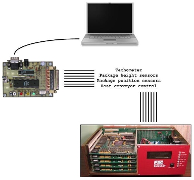
- at least one tachometer to measure the conveyor belt speed,
- up to seven photoeye sensors to determine package height,
- at least two additional photoeye sensors to determine the position of the package along the conveyor belt,
- one or two serial data links to the host conveyor control system
For example, the scanner could scan a barcode label on the 3rd package first, then the 12th, then the 1st, then the 10th. The software had to use the information from the photoeye sensors and tachometers to correctly determine which label was scanned from which package, and then transmit the data from each package when that package reached a certain point on the conveyor.

|
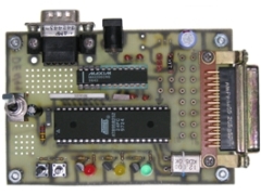
I developed a Windows program (using Borland C++ Builder) that would allow me to define how the various signals should act. This information was then sent from my desktop PC to the general purpose 8051 board. The 8051 board would then simulate the various signals and send them in to the barcode scanner. I could therefore change various parameters in the Windows GUI to simulate real world 'error conditions', and see if the barcode scanner would correctly handle them. The PC could not simulate the signals directly because PCs are not capable of generating signals with the precise timing that the barcode scanner system expected. See other projects I did at PSC HERE.